Difference between revisions of "RGB-Pi PLUS Installation"
(Marked this version for translation) |
|||
| Line 1: | Line 1: | ||
<languages/> | <languages/> | ||
<translate> | <translate> | ||
| + | <!--T:1--> | ||
'''VideoTutorial''' | '''VideoTutorial''' | ||
| + | <!--T:2--> | ||
[[Image:Plus_mini.png|link=https://www.youtube.com/watch?v=gGsKI9Mg9-Y]] | [[Image:Plus_mini.png|link=https://www.youtube.com/watch?v=gGsKI9Mg9-Y]] | ||
| + | <!--T:3--> | ||
'''Step by step''' | '''Step by step''' | ||
| + | <!--T:4--> | ||
{| | {| | ||
|- | |- | ||
Revision as of 16:52, 20 June 2021
VideoTutorial
Step by step
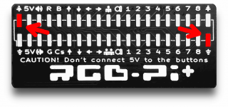
| 1. If you need to sold the male pins begin putting tin on thecontrary corners of the board and weld first this point to align the pin header, after you can continue welding the rest of contacts. |
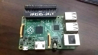
| 2. Connect the board to te pi in this position, to the outside of the Pi |
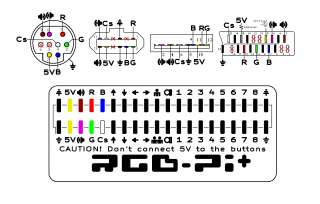
| 3. Begin wiring the video pins,, you can use you favorite plug. |
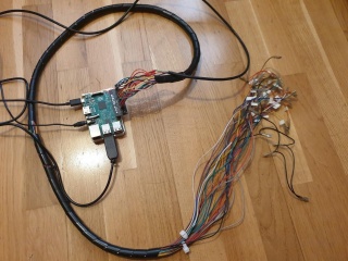
| 4. Create a bundle of cables as seen in the following to be connected to buttons and monitor. |
| 5. That's all! For instructions on how to install RGB-Pi OS, please visit the corresponding section in this wiki. |


