Difference between revisions of "RGB-Pi JAMMA Installation/es"
(Created page with "'''Paso a paso'''") |
(Created page with "{| |- |1. '''NO SALTARSE ÉSTE PASO'''. Inserta la pieza en forma de ┳ en el pin 7 del conector JAMMA hembra 320px|border320px|border |- |...") |
||
| Line 10: | Line 10: | ||
{| | {| | ||
|- | |- | ||
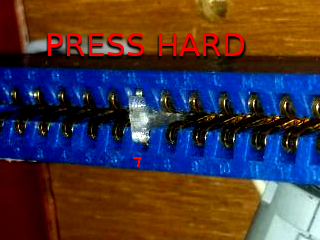
| − | |1. ''' | + | |1. '''NO SALTARSE ÉSTE PASO'''. Inserta la pieza en forma de ┳ en el pin 7 del conector JAMMA hembra |
[[File:T.png|320px|border]][[File:Tjamma.png|320px|border]] | [[File:T.png|320px|border]][[File:Tjamma.png|320px|border]] | ||
|- | |- | ||
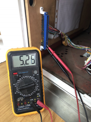
| − | |2. | + | |2. Con el RGB-Pi todavía '''DESCONECTADO''', enciende la maquina y ajusta el voltaje en el pin 3 a 5.25v |
[[File:tester.png|320px|border]] | [[File:tester.png|320px|border]] | ||
|- | |- | ||
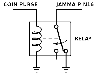
| − | |3. ''' | + | |3. '''Revisa si tu maquina tiene monedero electronico o ocntador de monedas''' en el el pin 16 y T, si éste pin te da 12v or 5v al introducir una moneda, esto '''puede dañar tu placa RGB-Pi''', Desconecta el monedero o contador de monedas o reemplazalo por un botón o por un relé. |
[[File:relay2.png|320px|border]] | [[File:relay2.png|320px|border]] | ||
|- | |- | ||
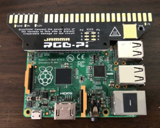
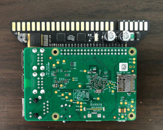
| − | |4. | + | |4. Conecta tu RGB-Pi JAMMA con tu Raspberry orientando el peine JAMMA hacia el exterior de tu Raspberry Pi |
[[File:jamma0.png|320px|border]][[File:jamma1.png|320px|border]] | [[File:jamma0.png|320px|border]][[File:jamma1.png|320px|border]] | ||
|- | |- | ||
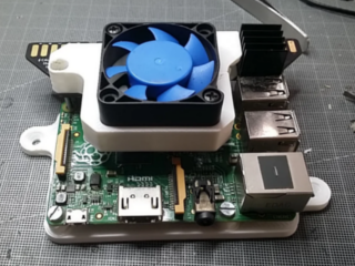
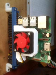
| − | |5. | + | |5. Si vas a utilizar niveles altos de sonido, deberias añadir un disipador del mismo tipo utilizado para la CPU de la Raspberry en el cuadrado amarillo marcado con un simbolo de calor, si tu nivel de audio es muy bajo o si instalas un sistema de ventilación [https://www.thingiverse.com/thing:3804116 como éste] entonces no sera necesario un disipador. |
[[File:fan.png|320px|border]] | [[File:fan.png|320px|border]] | ||
|- | |- | ||
| − | |6. ''' | + | |6. '''CON LA MAQUINA APAGADA''' conecta el RGB-Pi JAMMA a la maquina. '''NO CONECTES NINGUNA ALIMENTACIÓN USB A LA RASPBERRY''' |
[[File:recom2.png|320px|border]] | [[File:recom2.png|320px|border]] | ||
|- | |- | ||
| − | |7. | + | |7. Esto es todo! Para las instrucciones de como instalar el sistema, por favor visita la sección destinada a tal efecto [[Special:MyLanguage/OS_Installation|en ésta pagina]]. |
|} | |} | ||
Revision as of 16:27, 20 June 2021
VideoTutorial
Paso a paso
| 1. NO SALTARSE ÉSTE PASO. Inserta la pieza en forma de ┳ en el pin 7 del conector JAMMA hembra |
| 2. Con el RGB-Pi todavía DESCONECTADO, enciende la maquina y ajusta el voltaje en el pin 3 a 5.25v |
| 3. Revisa si tu maquina tiene monedero electronico o ocntador de monedas en el el pin 16 y T, si éste pin te da 12v or 5v al introducir una moneda, esto puede dañar tu placa RGB-Pi, Desconecta el monedero o contador de monedas o reemplazalo por un botón o por un relé. |
| 4. Conecta tu RGB-Pi JAMMA con tu Raspberry orientando el peine JAMMA hacia el exterior de tu Raspberry Pi |
| 5. Si vas a utilizar niveles altos de sonido, deberias añadir un disipador del mismo tipo utilizado para la CPU de la Raspberry en el cuadrado amarillo marcado con un simbolo de calor, si tu nivel de audio es muy bajo o si instalas un sistema de ventilación como éste entonces no sera necesario un disipador. |
| 6. CON LA MAQUINA APAGADA conecta el RGB-Pi JAMMA a la maquina. NO CONECTES NINGUNA ALIMENTACIÓN USB A LA RASPBERRY |
| 7. Esto es todo! Para las instrucciones de como instalar el sistema, por favor visita la sección destinada a tal efecto en ésta pagina. |
JAMMA RGB-Pi Pinout Serie4
   JAMMA / MVS
   ┏━━━━━━━━━━━━━━━━━┳━━━━━━━━━━━━━━━━━┓
   ┃GND             A┃1             GND┃
   ┃GND             B┃2             GND┃
   ┃+5V             C┃3             +5v┃
   ┃+5v             D┃4             +5v┃
   ┃                E┃5                ┃
   ┃+12v            F┃6            +12v┃
   ┃Key             H┃7             Key┃
   ┃                J┃8                ┃
   ┃                K┃9                ┃
   ┃Speaker - or L  L┃10 Speaker + or R┃
   ┃                M┃11               ┃
   ┃Video GREEN     N┃12       VideoRED┃
   ┃Video SYNC      P┃13      VideoBLUE┃
   ┃P2 Button 7     R┃14       VideoGND┃
   ┃                S┃15     Button7 P1┃
   ┃P2 Coin         T┃16        Coin P1┃
   ┃P2 Start        U┃17       Start P1┃
   ┃P2 Up           V┃18          Up P1┃
   ┃P2 Down         W┃19        Down P1┃
   ┃P2 Left         X┃20        Left P1┃
   ┃P2 Right        Y┃21       Right P1┃
   ┃P2 Button1      Z┃22     Button1 P1┃
   ┃P2 Button2      a┃23     Button2 P1┃
   ┃P2 Button3      b┃24     Button3 P1┃
   ┃P2 Button4      c┃25     Button4 P1┃
   ┃P2 Button5      d┃26     Button5 P1┃
   ┃GND/P2 Button6  e┃27 Button6 P1/GND┃
   ┃GND             f┃28            GND┃
   ┗━━━━━━━━━━━━━━━━━┻━━━━━━━━━━━━━━━━━┛
   *Pins 10 & L change depending on the position of the stereo/mono switch. For mono use + - and for stereo use R & L and common ground.
   *Pins 27 & e are connected to GND by default. To enable the same as the 6th button, cut the jumpers JP1 & JP2 on the board.
   Kick
   ┏━━━━━━━━━━━━━━━━━┳━━━━━━━━━━━━━━━━━┓
   ┃P2 Button4      4┃6      Button6 P1┃
   ┃P2 Button5      5┃5      Button5 P1┃
   ┃P2 Button6      6┃4      Button4 P1┃
   ┗━━━━━━━━━━━━━━━━━┻━━━━━━━━━━━━━━━━━┛
   *Take the ground from any pin of the harness


