Difference between revisions of "KickHarness"
m |
|||
| Line 1: | Line 1: | ||
| − | + | The KickHarness is an external connector for the JAMMA used in CPS boards to provide the games two extra buttons per player. | |
| − | + | How can we connect this extra cables in our RGB-Pi JAMMA? There are two available options: | |
| − | + | === 1. Through the jamma itself, transforming the same into a jamma+ model === | |
| − | |||
| − | |||
| − | |||
| − | |||
| − | |||
| + | On the jamma board, we have pins 26 and 27 for buttons 5 and 6 for player1 and <d> and <e> for Player2 | ||
┃P2 Button5 d┃26 Button5 P1┃ | ┃P2 Button5 d┃26 Button5 P1┃ | ||
| Line 15: | Line 11: | ||
┃GND f┃28 GND┃ | ┃GND f┃28 GND┃ | ||
┗━━━━━━━━━━━━━━━━━┻━━━━━━━━━━━━━━━━━┛ | ┗━━━━━━━━━━━━━━━━━┻━━━━━━━━━━━━━━━━━┛ | ||
| − | |||
| − | |||
In a standard jamma configuration we would find this: | In a standard jamma configuration we would find this: | ||
| − | |||
┃ d┃26 ┃ | ┃ d┃26 ┃ | ||
| Line 24: | Line 17: | ||
┃GND f┃28 GND┃ | ┃GND f┃28 GND┃ | ||
┗━━━━━━━━━━━━━━━━━┻━━━━━━━━━━━━━━━━━┛ | ┗━━━━━━━━━━━━━━━━━┻━━━━━━━━━━━━━━━━━┛ | ||
| + | Everything boils down to rewire the pins 27 GND and <e> GND to the 28 and <f> leaving free 26, 27, <d> and <e> for soldering some wires into a KickHarness connector. | ||
| + | |||
| + | === 2) Through the points located on the board === | ||
| − | + | The second option is connecting it to the points in the board with the labels P1B9 P1B10 P2B9 and P2B10. The name is self-explaining which one is for player1, player2 and its sorting. Button 9 and 10 are buttons 5 and 6 in the kickHarness and button 10, so we would solder the wires there to the connector. | |
| − | |||
| − | + | Once ended, we need to perform the remapping of the controllers. | |
| − | + | === Bonus Option === | |
| − | + | If you don't like soldering, there exists adapters for KickHarness to jamma+ which add the buttons through the jamma and include a voltimeter as an extra: | |
'''JNX v1.3 Atlas Adapter''' | '''JNX v1.3 Atlas Adapter''' | ||
[[File:Atlas.jpg|400px|thumb|left|Haz click para ampliar]] | [[File:Atlas.jpg|400px|thumb|left|Haz click para ampliar]] | ||
Revision as of 19:12, 1 May 2020
The KickHarness is an external connector for the JAMMA used in CPS boards to provide the games two extra buttons per player.
How can we connect this extra cables in our RGB-Pi JAMMA? There are two available options:
1. Through the jamma itself, transforming the same into a jamma+ model
On the jamma board, we have pins 26 and 27 for buttons 5 and 6 for player1 and <d> and <e> for Player2
  ┃P2 Button5      d┃26     Button5 P1┃
  ┃P2 Button6      e┃27     Button6 P1┃
  ┃GND             f┃28            GND┃
  ┗━━━━━━━━━━━━━━━━━┻━━━━━━━━━━━━━━━━━┛
In a standard jamma configuration we would find this:
  ┃                d┃26               ┃
  ┃GND             e┃27            GND┃
  ┃GND             f┃28            GND┃
  ┗━━━━━━━━━━━━━━━━━┻━━━━━━━━━━━━━━━━━┛
Everything boils down to rewire the pins 27 GND and <e> GND to the 28 and <f> leaving free 26, 27, <d> and <e> for soldering some wires into a KickHarness connector.
2) Through the points located on the board
The second option is connecting it to the points in the board with the labels P1B9 P1B10 P2B9 and P2B10. The name is self-explaining which one is for player1, player2 and its sorting. Button 9 and 10 are buttons 5 and 6 in the kickHarness and button 10, so we would solder the wires there to the connector.
Once ended, we need to perform the remapping of the controllers.
Bonus Option
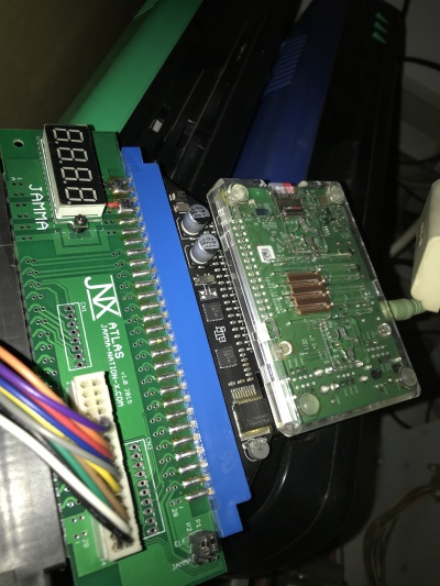
If you don't like soldering, there exists adapters for KickHarness to jamma+ which add the buttons through the jamma and include a voltimeter as an extra:
JNX v1.3 Atlas Adapter
